Selecting the best tool alloy to reduce molding cycles
Selecting the ideal mold material can immensely affect the injection molding process. Simulating different possibilities can save huge amounts of time and money while finding the optimal configuration.
Reducing the molding cycle in injection molded processes is a constant demand in the plastics industry, especially in the consumer packaging field where margins are even more tight.
The packaging molder Proplas S.A., based in Medellin, Colombia, was confronted with the task of molding a high demand cap for a personal care application. The initial mold cavity was made of common tool steel and the cycle time achieved was higher than expected. A reduced cycle time led to an incomplete curing because of the part contraction – making it unable to perform its sealing task in the package.
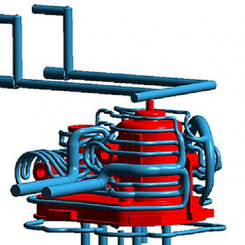
Proplas, SIGMASOFT® Virtual Molding customer since 2015, decided to look for alternatives to reduce the cycle time for this application. Including additional cooling channels was not an option as the planned ejection configuration left no space for additional channels. The mold design team decided to seek alternative high-conductivity alloys to channel the heat away from the cavity’s hot spots.
High conductivity alloys, such as copper beryllium, are expensive materials and difficult to manufacture. Since several parts had to be produced for the multi-cavity mold configuration, it was important to assess upfront whether the investment would pay off.
Because copper-beryllium alloys have lower resistance to thermal fatigue than steel, it was crucial to be aware of the maximum temperature achieved in the thermal peak of the process to avoid reaching a critical value.
SIGMASOFT® Virtual Molding helped the customer solving this task. Since the software reproduces every component in the mold with its exact material properties and, thus, virtually reproducing the complete molding process over several cycles, the thermal conditions achieved by different materials were clear.
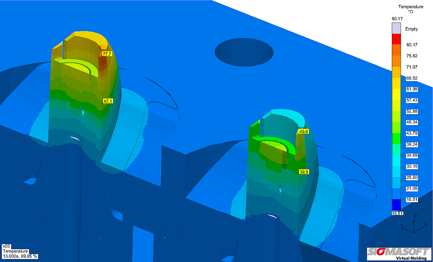
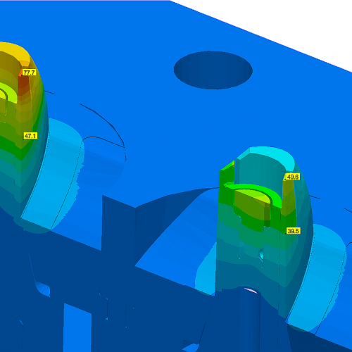
In Figure 1, the left side illustrates the temperature distribution in the initial mold configuration, made of conventional tool steel. As seen, a hot spot occurred at a location where the dimensions of the product where critical. This hot spot produced a larger shrinkage precisely at the part location where the curing had to be performed.
The right side shows the temperature distribution in the copper beryllium alloy. The residual heat in the critical location was substantially reduced, leading to a reduction of the peak temperature from 76°C to 49°C.
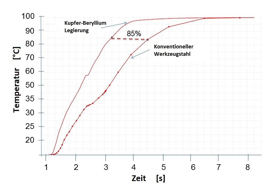
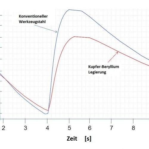
The temperature in the hottest spot of the cavity was monitored via virtual thermocouple. This software feature allows a virtual monitoring of any location in the mold during several molding cycles, helping to understand the effects on critical components. Figure 2 shows the temperature curves in both the original steel configuration and the copper-beryllium application. As can be seen, the highest temperature in the copper-beryllium mold was reduced, eliminating the risk of thermal fatigue in the cavity core.
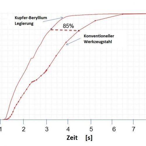
Additionally, it was important to understand the benefit achieved in curing. Figure 3 shows the progress of curing degree plotted against time. The curing time in the critical location was reduced from 4.7 s to 3.2 s, while still improving the part dimensional stability.
